A Sherline-based CNC mill

NickB

Western Thunderer
Why build a CNC mill? Why do anything in this hobby of ours? Because I was curious to do it, felt that there was a fair chance of success, and hoped to use it to make parts I needed.

I was familiar with CAD/CAM from my days in the engineering industry, not as a direct user, but I saw enough of it to understand the power and potential. I'm retired but retain an abiding interest in discovering what of the materials, methods and techniques used in that world can transfer into ours. Recognising that our budgets and facilities are much more limited, but - very important - time is NOT of the essence, and we can afford to get it wrong a couple of times along the path to getting it right.

Also, I was already using Fusion 360 for CAD and I knew it had some very powerful CAM features too. CNC isn't just about machines, it is about software and hardware and discovering how to get the best of both working together.

And I’d got to know @Mikemill who has a CNC mill, and he was generous with his time and advice. We collaborated on several occasions, me producing the machining files from CAD models and Mike doing the actual machining.

What about buying one? There are some small CNC mills on the market but their price today is high enough to blow the workshop budget for years to come, and they tend to be made overseas with all the potential problems of import and manufacturer support. There are a few bobbing around on the second hand market, often ex-education or training machines. Initially tempting, but they tend to be “closed systems” that come with their own operating system and software, and if something went wrong, could I get the components to fix it? In any case, I wanted to build my own!

IMGP1763.png

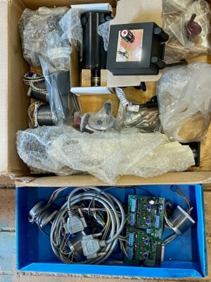
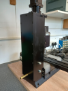
Thus it languished for some time, until one day the stars all came into alignment. I’ve been a long time user of Sherline equipment (the photo above shows my manual lathe and mill) and in the way of things, over time I had collected quite a few accessories and spare bits and pieces. One day I was offered, second hand, enough parts to form the basis of a second mill. At the same time Sherline had a sale on their own mill CNC upgrade kit. The dollar exchange rate happened to be particularly favourable at that moment, so even with taxes, duties and shipping, it was affordable.

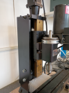
The upgrade kit replaces the lead screws with ballscrews with negligible backlash and has new carriages for all axes and mounts for stepper motors to drive the axes.

It all went together quite easily. I hit one snag but an email to Sherline was answered very quickly with just the information I needed. The quality of their customer service is such that others can only aspire to. Just thought I’d mention that.

IMG_20240516_152631115.png IMG_20240516_152652317.png

I bought stepper motors from one of many suppliers on the web, and the mechanicals were done. I'll talk about the electronics and the computer in the next installment. But of course you want to know if it worked. So did I! I did a temporary hook-up and made a few trials. There were celebrations that evening.

IMG_20240516_183000805.png IMG_20240811_122525585.png

To be continued.
Nick
 

Giles

Western Thunderer
Excellent! Although I went down a slightly different path (with a Stepcraft) a CNC mill really broadens the horizons, and I ended up making all sorts - large and small on the machine. Extremely useful!
 

Fitzroy

Western Thunderer
Interesting! A friend and I both did this about 15 years ago but the upgrade didn’t include ballscrews. Now there is quite a bit of backlash on mine and overhauling with new ballscrews would be a great idea. I notice the stepper motors look a lot beefier than the ones they used to offer too.
 

Mikemill

Western Thunderer
The point of using a CNC mill is you can make parts for all items used in a model railway, engines, coaches, wagons, signals, buildings, anything in your imagination in any scale.

The initial cost is high, but by the time you have built a couple of engines and wagons the rest are free.

The ability to design and produce your own parts is immensely satisfying and good fun.

Mike
 

NickB

Western Thunderer
Adrian - thank you for the link. It looks like a good deal.

Giles - I'm not familiar with Stepcraft, but the more options, the better.

Fitzroy - When they first released CNC, Sherline supplied the small motors, but now they recommend a larger motor, presumably from customer feedback. I chose a larger motor, but size means weight and the X axis motor in particular is suspended at the end of the table, so I didn't go too far.

Mike - As you know, if it wasn't for your example I don't think I'd ever have turned this dream into reality.

Nick
 

NickB

Western Thunderer
A CNC mill needs a lot more to make it useful. First, a way to create machining files, which I had nailed with F360 after I'd climbed another of those steep learning curves. A computer to run the machining files on and software to convert them into digital signals. A box of electronics to go in between the computer and the mill.

The electronics came from a web supplier again and comprised a controller card, drivers for each stepper motor, and a power supply. I’m not an electronics whizz but it was all pretty straight forward to hook up, particularly if you confine yourself to the basics and don’t get tempted to add lots of additional bells and whistles. I first of all put it together on the bench to make sure it all was working at it should.

IMG_20240516_152714134.png

IMG_20240516_182946300.png

Then I took it apart and put all the components into a proper enclosure.

IMG_20250515_162434347.png

A had a old laptop that I didn't use any more. If I hadn't, there are plenty of cheap pre-owned machines available. Low spec is fine, you need very little computing power to run the CNC software.

The software in my case is Mach3. It is a long way from the cutting edge today but it has a large user base which means if you ever have a problem (I haven't), somebody somewhere probably has the solution. One thing I discovered is that Mach3 was written to communicate with the CNC controller card via a parallel port on the computer. The old-style parallel port has largely disappeared but for some reason controller cards that use it are still widely available. But now cards are also available with USB and internet interfaces, both much better solutions. I chose USB. You need a patch to Mach3 to handle this but it is available as a free download.

IMG_20250515_163629715.png

I have probably made it all sound pretty simple, but in fact it was. I did all the wiring, checked it, double checked it, left it overnight, came back next day and checked it again. It paid off.

It helped that I kept it all to the basics. I have not got limit switches or zero detectors for reasons I'll explain later. I'd like to control the spindle speed in software but that may mean going into the Sherline speed controller, so I will leave that for another day.

It remains to talk about what I have used the machine for and some of the lessons learned, and about one major modification in the light of experience. Coming soon.

Nick
 

Attachments

  • IMG_20250515_162434347.jpg
    IMG_20250515_162434347.jpg
    345.3 KB · Views: 4

Fitzroy

Western Thunderer
Nick- Apologies if you have already mentioned it somewhere, but what sort of spindle speed are you running? I found to get reasonable feed rates and tool life with mild steel and tiny cutters I had to (as expected) go to crazy speeds. Only necessary because of the throughput I was trying to hit.
Piet
 

NickB

Western Thunderer
Piet, the max spindle speed is 2800 rpm. Yes, that is low by usual standards and does demand a corresponding reduction in feed rate. For me that is not a disadvantage because I'm happy to set it running and go do something else. Similar to how people run 3D printers. Throughput isn't a concern for me (my luxury).

That said, I feel that a higher speed, maybe twice the present limit, might be an advantage. The Sherline motor is controlled by an electronic speed unit (ESU) that they buy in from a third party supplier. I haven't found a replacement ESU that I can be sure works with this motor and won't overload it at higher speeds. An easier solution might be to change the pulleys. That's one for me to mull over in the future.

I haven't seen a problem with tool life though, again, that may be just me and my relatively undemanding needs. I buy cutters 10 at a time from China. They come razor-sharp and are so cheap that I replace them as soon as they start to dull.

Nick
 

D869Zest

Active Member
Nice job! I've CNC'ed my Proxxon MF70 and have found it very useful for 2mm scale work. I'm sure the Sherline is a significant step-up in terms of the mill.
 

Giles

Western Thunderer
Are you using the carbide D cutters by any chance? If so, you will need to check the actual diameters, as I find there is a significant variation from the advertised size!
 

Fitzroy

Western Thunderer
For speed, I found the high speed pulley upgrade solved most of my problems. That brought the speed up to 10,000 rpm with the same motor. That would be more than enough for one-off jobs or brass/NS/Ali. For production quantities and cutting steel I really needed much higher speeds and backing off on feed rates and also tool forces and fixture distortion so went to the air spindle kit which gives 50,000 rpm and is incredibly cheap considering the results.
 

NickB

Western Thunderer
D869 - thank you. The Proxxon is a very nice machine, but a bit too small for my work.

Giles - I've only ever used conventional fluted cutters, but thanks for the advice.

Piet - For sure the Sherline high speed pulley set would be the easiest to try. Maybe one day.

Nick
 

NickB

Western Thunderer
Now I was ready to start turning out parts, learning to use F360 and the mill together, exploring the various options and discovering the limits. In doing so, one thing I did notice was that the mill column would bend or twist under heavy cutting loads. There were lots of jobs where this was not a problem. But where it was, it was limiting the depth and speed of cut. I really wanted a solution.

I checked this by test cuts and measured the deflection with a dial gauge. It was not a huge amount, but enough to drag the cutter significantly off course and impair the accuracy and finish. It was not just the deflection, but also the sudden spring back when the load was removed. I didn’t break any cutters (lucky?) but I was concerned about the long-term wear and tear on the mill.

You can see from some of the previous photos that the column is actually quite light, and that was clearly the root of the problem. Some strengthening was required, but how to do that? The saddle is wrapped all the way round the column and the lead screw runs at the rear, leaving it almost completely inaccessible.

My solution was a substantial casing that would be attached firmly to the mill column base and support the motor mount which is attached to the top end of the column. The photos here show the platework, which was laser cut for me in 10mm and 15mm mild steel, and the mill column base which I drilled for two studs that would hold the casing.

IMG_20250426_164602430.png

IMG_20250426_125116577.png

Here is the casing in place. There is just enough access at the front to lubricate the leadscrew. Gib adjustment is much more easily done with the casing removed, but that should not be necessary very often. I sprayed it in satin finish black to match the rest of the mill.

IMG_20250515_161226792.png IMG_20250515_161130153_HDR.png

The motor mount is held in place with grub screws on each side. Originally I thought to replace the mount with a larger plate secured directly to the casing, but the whole Z-axis retrofit comes preassembled and realigning it would be tricky. I think my solution is helpful in allowing a little bit of adjustment. It has the added benefit of making it very easy to tram in the column.

IMG_20250515_162106907_HDR.png

Beefing up the column in this way has certainly been helpful in making it much more rigid. Rigidity is really, really important in milling, which is why industrial machines are truly massive things.
 

Attachments

  • IMG_20250515_161130153_HDR.png
    IMG_20250515_161130153_HDR.png
    483.7 KB · Views: 7
  • IMG_20250515_161226792.png
    IMG_20250515_161226792.png
    472.6 KB · Views: 9

NickB

Western Thunderer
You’ve got a CNC mill, what can you do with it? Not a lot, without a way to create machining files. My method is to use F360’s Manufacture workspace which can be used to create a CNC machining file from a CAD model. Since I mentioned F360, to be clear, and you have to these days, I have no connection with Autodesk, I just use their software for free like anyone else in my position can. There are inexpensive alternatives, e.g. SolidWorks, but I have no experience of them.

Let’s get going with a very simple component – a drawbar. It is a 2D component that can be made from a flat sheet of material. This is a screenshot of the toolpath that F360 generated, and in F360 it can be animated to see how the tool moves. I can “run” the program on the computer before cutting any metal. A few posts ago I said I hadn’t included any zero settings on my machine, and the reason is this software facility. All I have to do on the mill is to set the tool at the same location relative to the workpiece as its starting point in the file. The visual display shows exactly where the tool goes. I can be confident that it won’t unexpectedly zoom off, and that also renders limit switches unnecessary.

Screenshot 2025-06-05 182542.png

The toolpath includes several features that make life easier for the tool and the machine. When the tool moves vertically into the work, it does so not on a plunge but on a helical path. That means the cutting is always done by the flutes. and when it does that, it steps away from the work so as not to leave a mark on the finished part.

Tabs are easy to include, so that the finished part stays attached to the stock rather than pinging off into some dark corner of the workshop or worse, wrapping itself around the tool and breaking it. It’s not evident in the picture, but F360 modifies the feed rate as it goes, so as to reduce the load on the tool on entry and exit or when turning sharp corners, all in the cause of tool life and reducing breakage.

I’ve been through that in some detail, because the important message is that a sophisticated toolpath generator like this can compensate for inherent limitations in the milling machine. The whole is a lot more than the sum of the parts.

Here is the result of machining, ready to cut out and clean up.

IMG_20241107_100202340.png

Another example of some parts I made recently for an LNWR Lady of the Lake in 7mm scale:

Screenshot 2025-06-05 183838.png

And here are the finished parts (a few others have crept into the photo). The slots were done by hand. I don’t have a 0.5mm cutter and I have doubts that it would survive very long. But one day I will try it just to find out.

IMG_20250214_153941745.png

Nick
 

NickB

Western Thunderer
Making 3D parts is a lot more fun. Fun? Is that the word? … anyway, it’s a whole different ball game, as they say.

On the top of Webb tenders there were two injector controls, quite distinctive but also quite fiddly. Fortunately I had a photo of the preserved tender that was the basis of a CAD model. The model is simplified (yes, I do simplify) to make it machinable with infill below the operating arm and removal of the handle, to be added later as a separate component.

IMG_20210915_112452719.png

Injector control solid model.png

And here is the cutter path. Complicated enough? It’s a very small component so I was using a 1mm diameter cutter and to avoid lots of broken cutters, the maximum stepdown (the vertical distance between successive cuts) is only 0.1mm.


Screenshot 2025-06-06 203553.png


So the cutter is really just nibbling away. Each one took 90min to cut.


IMG_20241108_141540192.png

When the CNC had finished, I removed the excess stock by hand, removed the infill, and drilled for a separate handle. This cruelly enlarged photo shows them ready to be parted off.

IMG_20241110_123034333.png

Was it worth the effort? That’s something I don’t ask, let alone answer. It was a challenge and a problem and the fun (I’ve decided that is the word) was in solving it.

Nick
 

Overseer

Western Thunderer
Very nice. Not quite an injector control, well not directly. It is the operating part of a tapered plug valve. The valve itself is in the bottom of the tank with a vertical rod to the handle. The steps lift the valve to control the volume of water feeding the injectors. You have modelled it in the closed position, when running it would usually be partly or fully open. Similar fittings were very common on tenders and tanks on many railways.
 

NickB

Western Thunderer
Thanks, Overseer. Bill Finch calls it an injector water control so I borrowed his label. Yes, it's in the closed position but all the other cab controls are static too. You can't have everything ;)

Nick
 

NickB

Western Thunderer
Time to wrap up with some FAQs.

How much did it cost? £2700 to date. But that includes some existing parts that were reused and a very good deal on the mill upgrade kit from Sherline. To do it from scratch today would cost more than that.

What size of parts can you cut? The maximum cutting dimensions are about 160(X) x 80(Y) x 60(Z). Sufficient for the smaller scales, and I include smaller parts in G3 with that, but too limited for bigger stuff.

Where to start? I know nothing about CNC. Neither did I! Like most things, if you believe you can do it and are willing to learn, it is possible. Take small steps one at a time, and always go for the simple. Complications can come later.

What are the main features affecting the accuracy and quality of finish? For accuracy, ball screws every time. I looked at backlash compensation and anti-backlash nuts, but for me they don’t add up to a good solution. For quality of finish, rigidity, rigidity, rigidity. And sharp cutters.

What about software? If your ambitions go no further than 2D parts many CAD package will export a DXF file and there are convertors available to transform that into a machining file of G-code. A 3D package like F360 gives the many other possibilities that I have mentioned above. Personally it is my strong right arm and I would not be without it.

What developments would you like to have? For boiler fittings such as chimneys and domes, the problem is the saddle-shaped flange where it meets the boiler. To machine that effectively, you really need the ability to rotate the workpiece about its own axis. In the CNC world, that is A-axis rotation. The kit is available – Sherline sell a very nice rotary table – but F360 will only do the X, Y and Z axes. That is if you are using the free version. Give Autodesk lots of money every year and you can have the industrial strength version that unlocks the A-axis and many other features. I don’t know of any free alternatives. If you do, please let me know. I can’t justify the subscription cost for the few times I need it, so I have had to figure out ways to do without an A-axis. It’s doable, but it adds to the setup and running times.

Thanks for coming on the journey, If you've enjoyed it, thank @simond for prodding me into doing it.

Nick
 
Top