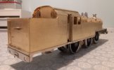
7mm Gladiator LMS/BR Fowler/Stanier 4P 2-6-4T

P A D

Western Thunderer
Thanks Duncan, so do I.

I just spend a lot of time cleaning up or solder on the inside where possible to avoid the need to remove the excess!

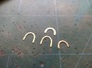
It's also good to solder details to main parts while they are off the model which leaves more room for cleaning up. The tank tops being a point in question. The etched parts were added in the flat and the castings were sdered from the underneath before i put the boiler in. The problem I have now is fitting the cast tank straps. If I solder them then it will be a pig to remove any excess to my satisfaction. With hindsight, I should have fitted them before the boiler when I could have soldered from underneath the tank top.:headbang:
I'll fix them with epoxy as any ooze is easier to remove.

Cheers,
Peter
 

SimonME30

Member
Thanks for documenting the build, Peter. I've got one of these in the stash, along with the David Andrew's Stanier 2-6-4T.
 

Genghis

Western Thunderer
Thanks for documenting the build, Peter. I've got one of these in the stash, along with the David Andrew's Stanier 2-6-4T.
I am having replacement toolbox etches produced: send me your contact details via the Gladiator website and I will send to you when they arrive.

David
 

P A D

Western Thunderer
Thanks for documenting the build, Peter. I've got one of these in the stash, along with the David Andrew's Stanier 2-6-4T.

Simon, my build of the DA Stanier 2-6-4T is documented here David Andrews 7mm Stanier 2 6 4 tank.

I am having replacement toolbox etches produced: send me your contact details via the Gladiator website and I will send to you when they arrive.

David
Many thanks David, but no need as I have scratched one up.
 

P A D

Western Thunderer
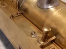
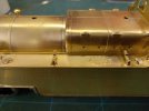
So here are the tank straps after fitting with epoxy. If I'd checked before fitting the boiler I would have discovered that there is clearance to fit them before the boiler and could then have soldered them from the inside .
20260103_170829.jpg

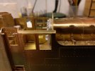
This is the etched bracket for bridging the gap between boiler and tank straps. The thin end fits in the strap and the wider end is fixed to the boiler. From looking at the drawings in the Wild Swann profile, this arrangement seems correct, but the bracket would have been fitted to the boiler not the cladding. Therefore I have only used the the thin ends of the brackets butted up to the boiler to give the impression that the bracket passes through the cladding.
20260103_170749.jpg

To give this.
20260104_213028.jpg

20260104_213115.jpg

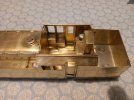
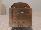
As mentioned in @SimonME30's thread on the Signature Models version of the Fowler 4P, the gap between the cab splashers is too narrow for the backhead casting( no doubt due to the narrow finescale frame width) so some material needs removing to get it to fit. Also the backhead is too short and needs some packing at the bottom to raise it up to the level of the firebox. On the other hand the reverser casting is too tall and need the base removing for it to sit at the correct height. 20260103_175620.jpg

20260103_175631.jpg

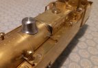
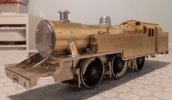
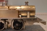
The chimney, dome and outside steampipes are now fitted as well
20260104_213304.jpg

Cheers,
Peter
 

Ian@StEnochs

Western Thunderer
If the straps are fixed to the boiler the cladding would need to have a cutout beneath the strap otherwise it couldn’t be fitted. Perhaps there was a filler piece slotted in after assembly?
Maybe I am just being pernickity!
 

Dave Holt

Western Thunderer
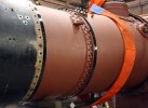
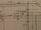
As the boiler cladding had joints top and bottom, it would be possible to fit them over the tank brackets through slots in the cladding. However, according to the cladding (boiler clothing) drawing, there were sort of inverted horse-shoe shaped detachable, indented patch plates local to the tank brackets, through which the horizontal part of the bracket protruded. The palm of the brackets was attached to the boiler barrel and was invisible once the patch plates were fitted. Looking at various photos, these patch plates don't really show up once fitted.
Dave.
 

mswjr

Western Thunderer
my guess looking at these pictures, is that the cladding sheets had cut-outs in them the same as holes for the washout plugs etc, they just fitted over the brackets on the boiler and would have been quite a good fit.
 

Attachments

  • Boiler-fit-8_1200px.jpg
    Boiler-fit-8_1200px.jpg
    294.7 KB · Views: 28
  • Two-crinoline-bands-fitted-around-the-boiler-barrel_1200px.jpg
    Two-crinoline-bands-fitted-around-the-boiler-barrel_1200px.jpg
    243.9 KB · Views: 28

P A D

Western Thunderer
As the boiler cladding had joints top and bottom, it would be possible to fit them over the tank brackets through slots in the cladding. However, according to the cladding (boiler clothing) drawing, there were sort of inverted horse-shoe shaped detachable, indented patch plates local to the tank brackets, through which the horizontal part of the bracket protruded. The palm of the brackets was attached to the boiler barrel and was invisible once the patch plates were fitted. Looking at various photos, these patch plates don't really show up once fitted.
Dave.

Hi David,
Looking at the drawing I see what you mean about the patches. I have also spotted them on one or two of the images in the Wild Swann profile, but as you say, they don't really show.
20260106_184208.jpg

The forward bracket can be seen here before the patch is added.
20260106_180123.jpg

This is how the kit depicts things, so on reflection not as wrong as I thought, although they look far too prominent if used (see image below from the Gladiator website).
20260106_174614.jpg

1000009826.jpg

With the above in mind I'm happy with what I've done, but I will make the patches from shim brass and see how they look.
20260104_213115.jpg

Cheers,
Peter
 
Last edited:

Overseer

Western Thunderer
The forward bracket can be seen here before the patch is added.
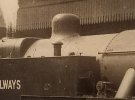
I think the photo shows the patch in place. My reading of the drawing and photo is that the ‘patch’ is a pressed steel piece screwed to the cladding. It is indented to provide access to the bolts connecting the two parts of the tank bracket. Cutting a larger odd shaped hole in the boiler cladding and soldering the kit part inside would be closer to the prototype appearance but better to leave it as you have made it. Certainly doesn’t need anything raised from the surface.
 

P A D

Western Thunderer
I think the photo shows the patch in place. My reading of the drawing and photo is that the ‘patch’ is a pressed steel piece screwed to the cladding. It is indented to provide access to the bolts connecting the two parts of the tank bracket. Cutting a larger odd shaped hole in the boiler cladding and soldering the kit part inside would be closer to the prototype appearance but better to leave it as you have made it. Certainly doesn’t need anything raised from the surface.

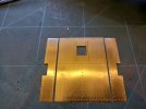
Having studied this image I would agree with your comments. The oval panels with indents can clearly be seen along with the screws fixing them to the cladding. As you say, it's probably best to leave things as they are. I suspect that as i did originally, John Firminger miss-interpreted the drawing when he was designing the kit.
20260106_221950.jpg

Cheers,
Peter
 

P A D

Western Thunderer
Time to fit the cab roof and steam pipes, but first some modifications. For the roof I use a method suggested to me a while ago by Tony Geary when I was building the David Andrews Stanier 4P.
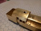
First the roof is cut either side at the rain strips. The side portions are fixed to the cab and the central part slots in under the rainstrips which are added from 2X1mm brass angle.
20260110_153517.jpg

Here's the cab after fitting the ranstrip to to the side portions and then fitting them to the cab.
20260110_192759.jpg

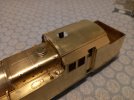
The inner edge of the rainstrips overhangs the edge of the side portions by 1mm which allows the edges of the central part to be slotted under the overhang to hold it in place. Care has to be taken to avoid getting solder under the overhang at the ends.
20260110_192819.jpg

And with the roof clipped in place.
20260110_192921.jpg

20260110_192935.jpg

The roof is held nice and tight and is of course removable for further detailing the cab interior and for painting.
20260110_194139.jpg

For the cast steampipes the kit provides half etched flanges for the top and bottom. As the come they are overly wide so I thinned them down before fitting. Three down one to go here.
20260110_143252.jpg

The cast brass pipes were epoxied in place and the flanges soldered.
20260110_193413.jpg

Still a bit wide I think but I couldn't go any thinner without loosing the rivets.
20260110_193547.jpg

The cab door handrails have now been fitted, but I've still to add the door handles.
20260110_193457.jpg

20260110_193440.jpg

20260110_193522.jpg

20260110_193338.jpg

20260110_193426.jpg

Cheers,
Peter
 

3 LINK

Western Thunderer
Amazing work as usual Peter, such a long over hang over the cab/bunker. I wonder how well they rode when in service..

Martyn.
 
Top