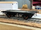
V2 4 wheel parcel van1/32 and G3

michael mott

Western Thunderer
Jigged up to make the braces, made replicating the ends much easier.
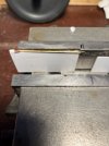
IMG_2904.jpeg
Then set up the home made mini drill for the holes before rounding the ends
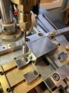
IMG_2906.jpeg
There is also a cross bar to tie the hangers together.
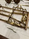
IMG_2913.jpeg
Next the prototype for the outer brake levers these are curved to give clearance around the axle. The brake shoe hangers and brake shoes will need to be made in order to complete the geometry of all the connections.

Michael
 

michael mott

Western Thunderer
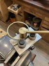
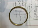
Since the brake shoes are going to be a fair bit of work to put together I began figuring out how to fabricate them. the space inside the open side is .091" and I just happened to have some .091" square brass in the brass drawer. next was to form the correct radius to match the wheel. I used the home made rail bender, it did not create a small enogh radius


so I popped in a couple of larger diameter bearings from the spare bearings drawer.

IMG_2916.jpeg

IMG_2914.jpeg
IMG_2917.jpeg

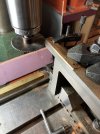
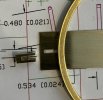
next a piece of brass to create the center section by making a channel that can be sliced into .091" bits and when set between the side plates will create the housing for the levers.
IMG_2919.jpeg
Michael
 

michael mott

Western Thunderer
Well now that I am able to get back to modelmaking and since I am building the "Cutlers Green" diorama and placing the unfinished V2 parcel van on the track I suppose that both need to go hand in hand. As any of you know picking up where one left off some time ago requires some head scratching while trying to remember how you did stuff. It was interesting rereading through this thread from the beginning last night and this morning to get back up to speed, and reflecting on comments on Richard's thread about the horse box clasp brakes. I will finish the linkages and set it all up now that I understand clearly how the brakes work. After working on the G3 model that is for the larger layout in the garage the G1/1/32scale model seems really fiddly and my hands more clumsy. Even more awe and respect for the 2mm lads and their incredible work. Now back to turning tiny .020 bolts and pins (visor time awaits today) after a good strong cup of coffee to spur me on this morning. Also check on how the FastMache dried up.
Michael
 

michael mott

Western Thunderer
A short video showing the working brakes

Now all I have to do is finish the other end and then connect the central brake link up through the floor into the body and a radio control servo to activate the brakes while it rolls along the track to stop it.

Michael
 
Last edited:

adrian

Flying Squad
Now all I have to do is finish the other end and then connect the central brake link up through the floor into the body and a radio control servo to activate the brakes while it rolls along the track to stop it.
Brilliant to see.

Just wondering is there any springing to assist the brake release? The reason I ask is that I'm adding brake detail to my Precursor chassis and underneath the ashpan I've spotted a small spring linked to the compensation crossbar on the brakes. It seems that when the brakes are "released" by unwinding the brake handle the springing is there to ensure that the brakes are actually pulled away from the wheel. Hence the thought about what happens on this vehicle.
 

michael mott

Western Thunderer
That is an interesting question Adrian, none of the drawings that have been posted on this thread show any springs to do that. The central lever when it returns pushes the brake shoe on the outer end away, I am guessing that the weight of the shoes will cause them to equalize away from the wheels once the vacuum is released, but in all honesty I don't know.
Michael
 

magmouse

Western Thunderer
Amazing work on the brakes, Michael. Regarding return springs, I don't know about these vehicles specifically, but when I was researching the brakes for my GWR Mink to diagram V12, I found that these had return springs retro-fitted some time after their 1906 introduction. I have several drawings showing GWR wagon brake gear around this time, and the earliest that shows a return spring is 1911.

I have no idea if passenger style brake gear of the sort you are modelling was similarly retro-fitted, or indeed had return springs earlier, though.

Nick.
 

michael mott

Western Thunderer
Thanks Nick for the info. I will be working again on the G3 version of this van once I finish this one for the small diorama layout. There are a lot of little compromises on this G1 version not least of which is the lack of any real frame members inside the plastic sole bars. As it is I have to move the outward ends of the inner support post braces to gain clearance for the long pull rods closest to the underside of the van body. Much of this smaller model was a learning curve to begin with and changes have been made to my Autocad Lt 2000 drawings since I started these two models. I suppose it would have been good to learn 3D cad drawing when I was younger but now I am ok with doing my design with paper and pencil and my old cad version, I just have to keep a windows XP computer running for it. so far its working out.
Michael
PS I learned cad with Generic cad back in 1985.
 

michael mott

Western Thunderer
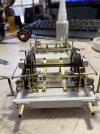
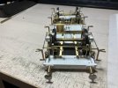
Now for the next interesting part , taking it all apart to paint.
IMG_3264.jpeg


I decided to blacken some of the parts so that painting kept to a minimum on all the small elements (I know huge compaired to Tim's tiny tube train)
IMG_3267.jpeg
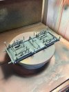
The plastic base with the glued on parts was washed in soapy water. tomorrow I'll set up the airbrush and give it all a dusting of a dull dark grey to unify the colour.
Michael
 
Top